Continuing last month’s technical theme, this month’s blog discusses another old chestnut; the effect of ambient temperature change (thermal effects) on hydraulic struts. Yes, the sun does occasionally shine on us in this country, not that you would think so in recent weeks.
We’ll be looking at two topics over the next two months: this month will cover why the load / temperature effects are independent of the actual prop length (with a few caveats); and next month progress on to look at how hydraulic props behave under change in temperature as compared to a non-adjustable structural steel member. So, let’s get down to business.
Thermal Expansion and Prop Length
Even the most hardened of temporary works engineers will sometimes hit a mental block when tying to rationalise how the calculation for increase load on a restrained strut when subject to a increase in temperature is actually independent of the length of the strut itself. In the end, it all boils down to the subtleties in the definition of strain.
Dredging the memory banks and going back to first principals. “strain” is an expression of a proportion, and thus it is unitless and dimensionless. Specifically strain (ε) is the ratio of the increase in length of a member (δL) to its original length (L0).
Equation 1.

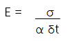
Strain crops up twice in the various algebraic expressions that govern thermal effects. In its most common usage, it appears in the derivation of Young’s modulus as stress divided by strain.
Equation 2.

It also occurs in the definition of the thermal coefficient of expansion (α) as induced strain per degree change in temperature (δt).
Equation 3.

Rearrange to give: ε = α δt
If we equate the two values of strain in Eq.2 and Eq.3 then it gives us a new equation from which we can derive force from temperature change.
Equation 4.
(rewrite with σ = F/A),
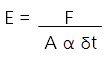
Equation 5.
Rearrange to give: F = E α A δt
We are now left with only variables for Young Modulus, Thermal coefficient of expansion (a known value for steel), Cross Sectional Area (a known value for a given steel section) and the measured variable, temperature change.
Looking at the equation, it’s now evident why load change (F) is independent of the prop length: there are no length variables! But to explain in words why this is the case is harder. Essentially: on one hand, a longer prop will extend or contract by a greater amount for a given temperature change; and on the other hand, a longer prop will compress by a greater amount when applying the same force. These two effects are inversely proportional and hence cancel each other out.
Another interesting concept that drops out of Eq.5 is that a heavier duty strut (bigger cross sectional area) will potentially induce a greater thermal load. So we have something of a vicious cycle in resisting thermal effects: using more steel to resist thermal loads, in itself generates yet more thermal load, if you see what I mean.
Moving on, another important factor to note is that we have, so far, assumed that the prop is fully restrained at its ends against movement due to expansion. Looking at this diagrammatically:
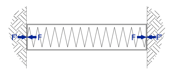
Fig.1.
Fig.1 above shows the strut in equilibrium at installation temperature. There is of course a certain amount of load in the strut from pre-stress and lateral earth pressures etc. If the temperature in the strut now increases as the sun comes out, it would want to expand, generating resisting forces from the surrounding ground.
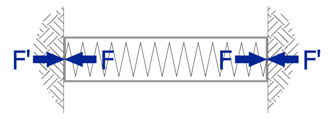
Fig.2.
Fig.2 above shows the scenario expressed by Eq.4 where the strut is fully restrained by a rigid support structure and all of the potential expansion from temperature effects is translated into extra axial load. Think of tales of railway lines buckling on hot days as an analogy.
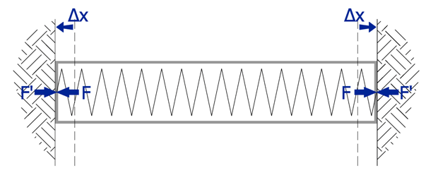
Fig.3.
Fig.3 above shows the alternative scenario where the strut is only partially restrained by a semi-flexible support structure which allows the strut to expand to a degree; In this case, the load induced in the strut is reduced.
There is published guidance to help engineers assess the degree of restraint afforded by various wall construction types e.g. diaphragm walls, sheet piled walls. These reduction factors (B) are applied to our Eq.5 to calculate theoretical additional load effect that we need to include in the design of our temporary works strutting system. That is:
Equation 6.
F = B E α A δt
That is probably enough for this month. Next month we will extend this accepted theory to consider how a strut with a load resisting hydraulic ram behaves under thermal induced loading as in the photograph below.
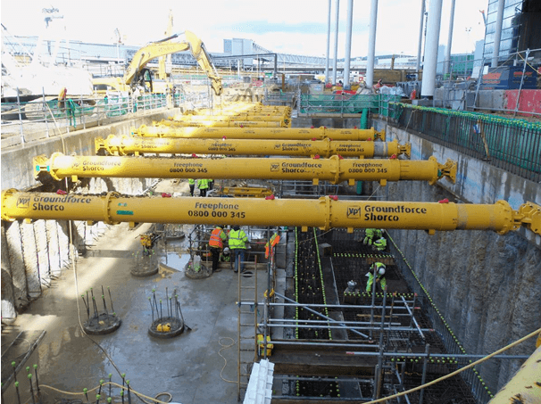
Fig 4. Groundforce hydraulic props supporting a "stiff" retaining structure
i.e. a RC capping beam on top of concrete bored piles