After a bit of a summer break its time to put pen to paper again on the technical aspects of shoring equipment.
The last two blogs have focused on trench box design, so to complete the picture; I will go through the basic design principals of the increasingly popular rolling strut box and slide rail products that we supply.
Rolling strut (RS) linear support systems are available in either slide rail or trench box formats and offer a number of advantages over their traditional fixed strut counterparts in terms of strength and functionality.
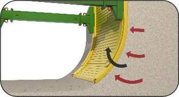
The system employs a single (rolling) strut assembly at the front and rear of the plates which as the name suggests, is able to slide or roll up down vertically. Much greater versatility can thus be achieved enabling larger and longer pipes to be installed with rolling struts compared to standard trench boxes.
The multi position rolling strut concept however does add a level of complexity to the determination of structural capacity (or overall resistance to lateral earth pressures) of the unit.
One can appreciate that the overall box capacity will be dependent on the position of the strut within the post. It is therefore “safer” to specify its capacity when the strut is positioned so as to induce in the most onerous forces in the supporting components. This is generally with the strut at its uppermost position. As with traditional trench boxes, capacity or resistance is usually quoted in terms of allowable uniform panel pressure. Should the designer wish to carry out an analysis with the strut positioned lower down in the posts to give higher system capacity, it is necessary to carry out a more rigorous structural analysis as described in the following sections.
Failure Mechanisms
 Both RS slide rail and boxes incorporate three basic structural elements, posts, panels and struts. In the case of boxes the posts are incorporated into the panels themselves. There are three main potential failure mechanisms in a simple box assembly namely:
- Inward bowing of the box panel between the struts - Bowing moment (denoted M1)
- Bending of the post under the strut - kicking moment (denoted M3)
- Failure of the strut;
Design considerations for panels
 The overall structural capacity of the box or slide rail is the least value to induce failure due to the following:
Bowing of the panels (M1). This is determined by the bending strength of the panel in the plane of bending. Panels are typically of cellular construction and it the strength is proportional to the section modulus of the component parts in the plane of bending (or bowing).
Bending of the end posts (M3). The panels themselves have little natural strength in this (vertical) plane of bending. RS box panels incorporate strengthened end posts to resist kicking moments whilst slide rail system used separate posts.
Design considerations for rolling struts
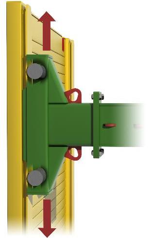 Both RS box and slide rail use the same basic design of rolling strut all be it of different sizes and capacities. The strut assembly comprises three basic components namely left and right hand roller carriages connected together by rectangular fabricated flanged box section spacers of variable width as illustrated in the photograph opposite.
In their simplest configurations both RS slide rail and box systems use a single strut in each post therefore the struts themselves have to be capable of resisting large bending moment (induced by kicking moments) as well as axial compression induced by lateral pressure on the panels
Considering the overall capacity (or resistance) of the RS assembly; there are typically three potential modes of failure;
- Local failure by overloading of the roller contact points in either tension or compression,
- Combined bending / axial failure of the box section extension bars
- Failure of the bolted joint
Note that RS struts are not susceptible to lateral torsional buckling failure due to their rectangular hollow section type of construction.
RS Design verification
Once the site specific geotechnical calculations have been completed in order to determine lateral forces on the system, it is relatively straightforward to create a simple statically determinate structural model of the RS systems from which the design effects on the various components can be calculated. It is then a matter of comparing these to the quoted resistance values for the various components using the limiting value as the measure of overall system capacity.
Summary
The ability to position the rolling struts in various locations adds a degree of complexity to the determination of overall RS system capacity or resistance when compared with conventionally strutted box systems. Published values for capacity relate to the strut being positioned in its most onerous location, that is when it is raised to its highest point. This will induce the largest kicking moments in the support posts and greatest bending forces in the struts. When the struts are to be positioned lower down the posts it will be necessary to carry out a more rigorous check on individual system parameters. This will produce greater values for overall system capacity.
Ok, so there you have it, everything you need to know about rolling strut systems.
Next blog we will depart from boxes back on to hydraulic systems. Before I finish, just a quick plug about the forthcoming GE promoted Basements and Underground conference for which we are main sponsors. Hope to see you there.
Comments
Blog post currently doesn't have any comments.