One of the many projects we are desperately trying to complete at present is the launch of our new technical file. Whilst drafting out some guidelines relating to the design of trench boxes, it struck me that this would make an ideal technical yet easy going blog submission.
“Boxes” are by and large are used (and abused) on most construction sites at some stage. Being a standalone piece of kit (unlike sheets and frames), the design philosophy on boxes is that they are strong enough to cope with most ground conditions within their operating scope. We have noticed a big increase of late in requests to provide site specific design calculations to support their use. So how do we go about this?
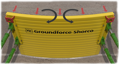
All trench and manhole boxes are designed as standalone products. It is therefore common practice to simply specify the structural capacity of trench and manhole box systems by the allowable uniform panel pressure that the panels can sustain over the full panel area (see fig 1 above). Basic verification calculations can be completed very quickly by simply comparing the worst case calculated soil pressure with the allowable panel pressures.
Whilst this approach simplifies structural verification, and will provide a safe solution, it can lead to pessimistic answers, consequent over-design and situations where boxes appear not to be strong enough where a more rigorous analysis will prove that they are perfectly adequate. The latter is a common situation in deeper excavations and /or ground conditions are poor.
Failure mechanisms
Boxes generally comprise just two structural elements, side panels and struts, the latter usually incorporating some form of
mechanical adjustment facility.
There are three main potential failure mechanisms in a simple box assembly namely:
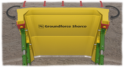
- Inward bowing of the box panel between the struts - Bowing moment (denoted M1) – see fig 2.
- Bending (in plan) of the end return panels (denoted M2) this applies to manhole boxes only
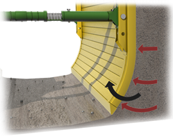
- Bending of the panel under the lower strut - kicking moment (denoted M3)
- Failure of the strut in compression (either buckling of local component failure) or in tension.
Design considerations for panels
Consider resistance to M1 bowing. This is determined by the bending strength of the panel in the plane of bending. Panels are typically of cellular construction and it the strength is proportional to the section modulus of the component parts in the plane of bending
Consider resistance to M2 bending. This is determined by the specific construction detail of the manhole box panels in the comers. Generally M3 bending is not a critical factor in determining the limiting box capacity.
Consider resistance to M3 bending. Box panels themselves have little natural strength in this (vertical) plane of bending. It is simpler therefore to ignore this and relate M3 bending resistance to the strength of the end posts which also double up as strut housings. M3 bending capacity of each panel is therefore twice the bending resistance of the end posts.
Resistance of the various types of struts available is slightly more complex and I will discuss this next time.
On a more personal note, after what seems like months of preparation and a very nervous and protracted wait, I have finally been accepted as a Fellow of the institution of Civil Engineers (FICE). I consider this to be a great honour as it is the highest grade of ICE membership. I look forward to the official award ceremony at Great George St in the autumn.
It just remains for me to wish you all a happy and restful Easter break.
Comments
Blog post currently doesn't have any comments.