Constructing a new building in a city centre requires a great deal of expertise if disruption to nearby residents and businesses is to be minimised. Speed and efficiency are key to getting the job done with the minimum of fuss and are essential to delivering the project on time and to budget.
Even more important is that the construction work does no damage to neighbouring buildings. This is especially true if the project entails excavating a large basement in close proximity to adjacent buildings and structures, since any ground movement can seriously affect the stability of nearby buildings.
When planning work of this nature, engineering design must be of the highest calibre.
The Project
 Main contractor Sir Robert McAlpine (SRM) is currently nearing completion of its £26.3 million contract for the first phase of the redevelopment of the Glasgow School of Art.
The site, opposite the school’s Grade A listed Charles Rennie Mackintosh building in the city centre, was previously occupied by three buildings which have been demolished.
The new 11,000 sq m building, designed by Steven Holl Architects of New York, is scheduled for completion in the summer of 2013. Project manager is Turner & Townsend.
The Challenge
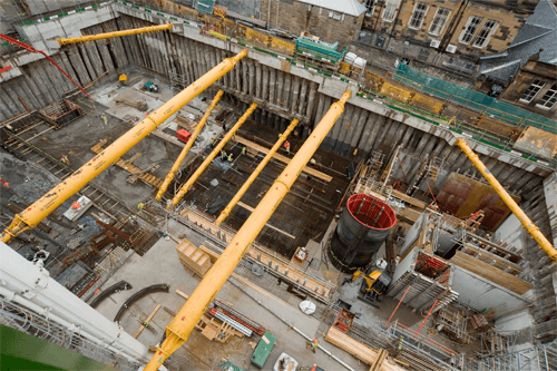
The new building features a double storey basement constructed in an excavation measuring approximately 60m long, 34m wide and 10m deep. During construction of the basement, SRM needed to support the sides of this excavation and to prevent any movement in the surrounding ground.
Traditionally, the contractor would have chosen a bespoke steel frame and tubes to provide the support to the contiguous piled wall. But while this would provide the support required, it would be time consuming – not only taking time to fabricate, but also slow to install and dismantle.
The Solution
SRM’s search for the ideal solution led them to the Major Projects Division at Groundforce Shorco. The Groundforce design team worked closely with SRM to develop a propping solution which was not only comparable in price to the cost of structural steel but also offered the additional benefits of rapid installation and decommissioning.
The design called for a total of nine modular hydraulic props bearing on waling beams around the perimeter of the excavation. There were six props at the upper level, which were connected to the capping beam, and three props at the lower level, which came off a steel waling beam on one side and spanned across to a mass concrete wall on the other. Originally SRM had envisaged six props in the lower level but by utilising Groundforces’s Load Monitoring system and adopting an observational approach, they were able to reduce this down to three, leading to cost and time savings.
The advantage of this system is that the props can be pre-assembled and quickly lifted into position, then hydraulically extended to provide the necessary lateral support.
In order to compare actual loads to design loads, Groundforce also supplied their unique Wireless Load Monitoring system. This gives a real time read out of prop loads and ambient temperature and alerts the contractor if pre set trigger levels are exceeded.
An additional concern of SRM’s was the possible effect of ground movements on neighbouring buildings. The site is located on a steep hillside meaning that the lateral loads varied at each level of the excavation. SRM needed an economical solution that would be quick to install, quick to remove and which would maximise working space within the excavation while providing assurance of adequate all-round support.
The Equipment
 SRM produced design loadings for all the required supports and Groundforce then specified props of the appropriate load capacity.
This resulted in a design employing eight 250 tonne capacity MP250 props and one 150 tonne HSK150 unit. The MP250 is Groundforce’s largest standard hydraulic prop and is generally supplied with 610 mm diameter tubular steel extensions to give the required length.
However, the two upper-level props, which were required to span the maximum (31.5 m) width of the excavation, were fitted with Groundforce’s 1220mm diameter “super-tubes”. These give the required stiffness across wide spans without the need for intermediate vertical supports which would interfere with structural works in the basement below.
The Groundforce Wireless Load Monitoring system allowed SRM to measure the effect of the basement excavation on the surrounding buildings.
This system – the first of its kind in the UK - uses electronic load pins to log prop loads and transmit readings to a central server via GPRS. This data is then displayed in the form of charts and graphs on a secure website which the client, and any other authorised users, can access at any time.
Using the modular hydraulic system in combination with active load monitoring allowed Groundforce and SRM to remain flexible, changing aspects of the design to accommodate changes to the construction sequence.
The wireless load monitoring system allowed SRM to adopt an observational approach to the lower level propping and significantly reduce the number of struts required. This had the resulting benefit of shortening the construction program for this phase of activity.
I’ve worked with smaller equipment, like hydraulic manhole braces, many times before, but this is a whole different order of scale Instead of handling units weighing 250 – 500 kg, you’re handling pieces weighing 16 or 18 tonnes. But it’s very user-friendly and everything’s gone very smoothly.
Peter Unwin, Construction Manager - SRM
Technical Support
Throughout the development and execution of this scheme, SRM and Groundforce site teams worked closely, developing a good working relationship.
A high level of attention to detail is required to ensure the system not only meets the design criteria but is delivered to site in the correct configuration and sequence.
The Major Projects Co-ordination team provided onsite assistance at all key stages, assisting with the prop installation and the set up and maintenance of the wireless load monitoring system.
Download PDF